Basis of Working Electrode

Basis of Working electrode


General Remark

1.General Remark

Laboratory Of Research & Development, BAS Inc.
Professor Noriyuki Watanabe

We will describe some tips in using working electrode in following series of letter. It is not appropriate to distinguish which one is working electrode or counter electrode whenever we employ a system of two electrodes. In that case, it is just possible to discriminate them as anode or cathode. However, it is still unable to say exact values of potential of both anode and cathode, so that it remains uncertain whether purposed reaction is occurring or not. It is important to examine redox potential corresponding to intended reaction, for which the potential of working electrode should be measured.

Distinct difference between working and counter electrode is applicable under using potentiostat. We can define the potential of a working electrode versus a reference electrode under so-called three electrode configuration (as shown in Figure below) by controlling with potentiostat. The understanding about potentiostat is desirable, even if not saying indispensable, which will be given later time.
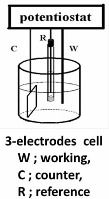
 

Although only connecting a platinum wire, which is immersed in a test solution, to the reference terminal of potentiostat makes electric contact with the test solution, so called pseudo-reference electrode, but that could not guarantee the stability or reproducibility of potential measurement. It might be worthy to note that reproducible measurement is possible only by connecting a reliable reference electrode.

We receive often the question that how the potential of counter electrode is going. It is quite reasonable question. The answer to this question is as follows. Amount of current flow in working electrode is exactly the same in counter electrode. The difference is just oxidative or reductive. If the current in working electrode is reductive (oxidative), the one in counter electrode should be oxidative (reductive). Hence, if depolarizing material (whatever it is) on counter electrode side without respect with either oxidative or reductive is scarce compared to the reaction of working electrode side, the overpotential in counter electrode side may glow exceedingly resulting in violation of compliance voltage. This difficulty can be mitigated by increasing the surface area of counter electrode in order to decrease current density. This is the reason why counter electrode with large surface area compared with working electrode is recommended, especially for large current application like bulk electrolysis.
Reference electrode detailed


Polarizable electrode and nonpolarizable electrode

2. Polarizable electrode and nonpolarizable electrode

Laboratory Of Research & Development, BAS Inc.
Professor Noriyuki Watanabe

Electrodes can be divided into two types: polarizable and non-polarizable electrodes.

The characteristic of an ideal polarizable electrode is that no faraday current flow when the electrode potential is varied. This type of electrodes usually can be used as Working or Counter electrodes.

The feature of a non-polarizable electrode is once the electrode potential be changed, the Faraday current flows out. In generally, this type of electrodes can be used as Reference electrodes.

An ideal polarizable electrode can be represented by a capacitor (condenser) in equivalent circuit as shown in Fig. 1-1. However, the extremely weak current flows at an actual polarizable electrode indeed. Therefore a high value resistance (Rhi) is required to parallel with the capacitor to represent the actual polarizable electrode in equivalent circuit [Fig. 1-(2)].

If a redox species coexists with the polarizable electrode, the redox reaction of species is occurred on the electrode surface and the Faraday current flows under the certain potential. In this case, a potential depending variable resistance (RF) should be added to the equivalent circuit in parallel. Furthermore, the effect of the species diffusion should be included, and a Warburg Impedance element is connected to Faraday resistance (RF) in equivalent circuit [Fig. 1-(3)].

Figure 1 is a schematic view of above description. In the absence of a redox system, even electrode potential has been changed, the capacitance and high resistance parallel circuit could still be maintained, this variable potential range is so called as potential window.

The wide potential window of the polarized electrodes is a very important condition in practical application. Platinum, Gold and Carbon (e.g., glassy carbon etc.) electrodes can meet this condition in general.

Equivalent circuits of the polarizable electrode. 


Gold, Platinum and other metal electrodes


CV of various metal electrodes in sulfuric acid solution.
Platinum is the most common polarizable electrode material, due to its high stability in physical and chemical properties. Hydrogen generation in reduction zone should be noted when the Pt used in aqueous solution. In addition, a proton adsorption process accompanied with the pre-step before hydrogen reduction should be cared. In oxidation zone, oxidation occurs at electrode surface and generates a corresponding reduction current.

This redox paired phenomenon can be founded in most of the solid metal electrode.

When the concentration of the target component is very low, such background current will interfere the measurement and the potential window becomes narrow. Although the electrode potential window is theoretically regulated by the electrode capacitance potential range, there should be no influence for the application if the background current does not interfere to the measurement.

Incidentally, figure 2 in above was borrowed from the old literature, negative potential located at the potential axis right side which was known as the classic graphic display method. This reflected the epoch in which the polarography was popularly used in the metallic ions reduction. Currently, the opposite direction graphic display of IUPAC is mainly used (positive right).


Usually used working electrodes & features

3. Usually used working electrodes & features

Laboratory Of Research & Development, BAS Inc.
Professor Noriyuki Watanabe
 
 
Contrasting to aqueous electrolyte solution, in non-proton organic solvent, platinum electrode can be used in a wide potential range without any proton adsorption desorption and hydrogen evolution reaction occurring. It is necessary to be considered in advance, when high concentration of chloride ions are contained in aqueous solution, dissolution of platinum metal is occurred, due to the formation of chloroplatinic acid ion at high oxidation potential.

Same as platinum, gold is commonly used electrode material. The difference is that gold does not have any proton adsorption-desorption waves, and the over-potential for proton reduction to hydrogen formation is much higher than platinum, therefore the potential window of gold in aqueous solution is wider than platinum in reductive direction. Similar to platinum, in aqueous electrolyte solution containing high concentration of chloride ions may cause the gold metal dissolution due to the formation of gold chloride acid ion at high oxidation potential. Because the surface of gold can be easily chemical modified by the thiol compounds, it has been used for the purpose of many research fields.

Carbon which is usually used electrode material same as gold and platinum, has many types. Such as graphite, pyrolytic graphite, highly oriented pyrolytic graphite (HOPG), glassy carbon and boron-doped diamond electrodes etc. Glassy carbon is the most commonly used electrode material among them. Significant progress regarding the carbon electrode surface analysis and chemical modification is expected to explain in detail in the next future article. 

Metallic mercury is liquid state at room temperature, accumulated mercury may drop down through the capillary by gravity, and it is used as repeatedly dropping microelectrode (dropping mercury electrode) in most cases. It is also frequently used as a stationary suspension electrode (hanging mercury electrode). This is the classic polarography. 
Mercury is a pioneer electrode by which the electrochemical reduction analysis methods being developed up to today. Mercury electrode surface is smooth up to atomic level, and it is possible to prepare a high surface reproducibility electrode. Since the over-potential for the reduction of hydrogen ions is large, it is utilized for many heavy metal (Pb, Tl, In, Cd, Sn, Zn, Ni, Cu, Mn, Fe, Co, Sb, Mg, Ca, Sr, W, etc.)ions reductive detection. Mercury can not be used in oxidation area, due to the oxidative dissolution of mercury itself. Gold electrode surface coated with mercury is amalgam electrode, on which the heavy metals ions can be detected in high sensitivity using anodic stripping voltammetry. However, from the viewpoint of environmental pollution, mercury environmental standards are extremely strict and difficult for mercury use in Japan.

The typical working electrodes generally used in electrochemical measurements are described above and it is of course be able to use other types of electrodes for special purpose. In corrosion research field, iron electrode is used for polarization measurement of Tafel plot, a nickel electrode and a nickel titanium alloy electrode are used for selective detection of carbohydrate in alkaline solution etc. examples are not shortage in the enumeration. The point is any materials can be used as working electrode in proper applications according to the research purpose.
 
Carbon electrode materials

4. Carbon electrode materials

Laboratory Of Research & Development, BAS Inc.
Professor Noriyuki Watanabe


Graphite is one of the crystalline forms of carbon element, just like the benzene ring condensation together plane (multiple hexagonal honeycomb) overlapping in layers (sp2 carbon). The benzene condensation similar plane is called basal plane, and the surface at perpendicular direction is called edge plane with layer appearance. 

The physical quantity along the basal plane and the edge plane are anisotropy. The electrical resistance along the basal plane is smaller than along the edge plane. Thus, the electrode properties are different for basal plane and edge plane electrode surface (edge plane electrode has better conductivity).

Furthermore, the capacitance of the electric double layer on electrode surface are different, the electric double layer capacitance of the basal plane electrode surface is smaller.
 Carbon electrode materials
Fig.4-1 The schematics of Graphite and Glassy carbon structure.


• Pyrolytic graphite (PG) is prepared by decomposing the hydrocarbon gas at the high temperature substrate. Pyrolytic graphite further dealt with high temperature and high pressure could be enhanced in the crystalline ordering, and highly oriented pyrolytic graphite (HOPG) can be obtained. The electrode performance is depended on the crystalline orderly ratio State of electrode surface can be detected by redox peak potential difference (ΔEp) in cyclic voltammetry (CV) diagram of ferrocyanide/ferricyanide. If the redox peak potential difference is higher than 700 mV (1M KCl supporting electrolyte solution, potential scan rate 0.2V/s), this surface is regarded as the basal plane of the highly oriented pyrolytic graphite (HOPG) (the peak potential difference of commonly used graphite electrode is around 60 mV). It is known that faster the electron transfer is, smaller the peak potential difference (ΔEp) will be, because the electron transfer rate on basal plane of the highly oriented pyrolytic graphite (HOPG) surface is very slow, that is why the large ΔEp value is appeared.

• Glassy carbon (GC) is the most commonly used electrode material, the structure of glassy carbon is shown in Fig. 4-1 (the left lower schematics). A lot of graphite structure shaped thin strip intertwine with each other in glassy carbon, although the microscopic structure has orderly morphology, but the macro structure can be regarded as amorphous (glassy) carbon. Therefore, as the electrode materials, allotropes of carbon are sp2 carbon in graphite structure (excluding diamond electrode). The surface of glassy carbon electrode (GC) is the mixture of basal plane and edge plane. Glassy carbon (GC) is dense and hard as glass, without gas or liquid permeability. In contrast, highly oriented pyrolytic graphite (HOPG) has a slippery flexible structure along the edge plane, peeling along the basal plane, a fresh surface can be obtained.

• Carbon paste is obtained by dispersed graphite powder in oil to paste state , can be used as an electrode (carbon paste electrode).

• Carbon fiber used for electrode preparation is called carbon fiber electrode. Usually, carbon fiber is used for microelectrodes preparation. Embedding the carbon fiber into the plastic or glass, after cutting, a cross-section is used as a microelectrode. Including glassy carbon, the basic structure is sp2 carbon bond.

• Positive holes in valence band are produced and conductivity is generated when boron element is mixed into sp3 bonded diamond (so called as boron-doped diamond electrode. If nitrogen element is incorporated, electronic conductivity is occurred.). A boron-doped electrode especially has very wide potential window. It has chemical stability like diamond, and can be used for special applications.

 
Structure of GC & Electrochemical features of basal/edge plane

5. Structure of GC & Electrochemical features of basal/edge plane

Laboratory Of Research & Development, BAS Inc.
Professor Noriyuki Watanabe


Carbon electrodes has been extensively studied by R.L. McCreery (He did research work in Ohio State University until 2006, currently is in University of Alberta. He obtained his Ph.D. degree under the direction of Professor Ralph Adams, a solid electrodes research pioneer in Kansas University). Their research achievements will be introduced and divided into several times.

Although the most commonly use glassy carbon (GC) material has a graphite structure in microcosmic viewpoint, it has an irregular structure in macroscopic viewpoint which is easily imagined from its name.

Benzene ring condensation together plane (multiple hexagonal honeycomb) in two dimensions are overlapped by layers. The benzene condensation similar plane is called basal plane, and the surface at perpendicular direction is called edge plane which has layer appearance. Knowing the different responses of basal plane and edge plane is helpful in understanding the GC.
 Basal and Edge CV
    Fig. 5-1 CV comparison of Basal and Edge plane.

Fig. 5-1 Showed the results obtained by measuring Co(phen)32+/3+ using basal plane and edge plane of HOPG (McCreery et al., Anal. Chem., 64, 2518, (1992), McCreery, Chem. Rev., 108, 2646 (2008).

The electron transfer rate calculated from the difference of the redox peak potential (ΔEP) are differed in 3 orders, and the electron transfer rate on basal plane is obviously slower.

Even if a new basal plane is obtained by peeling, due to the peeling operation and the increased stress when the electrode was assembled into the mold, obtaining an ideal basal plane is extremely difficult.

Therefore, McCreery et al. did the measurements by using a special method known as an inverted drop cell (see the cited literature if interested).

Three different basal plane orderliness electrodes were compared by using potassium ferro-ferricyanide sample, as shown in Fig.5-1. The orderliness decreased from A to B and C.

ΔEP (oxidation-reduction potential difference peaks) of the potassium ferro-ferricyanide cyclic voltammogram measured with high orderliness A is about 700 mV (the electron transfer rate becomes slower and ΔEP becomes lower) Large. The potential difference of the reversible reaction is 59 mV at 25°C).


 Basal and Edge CV

Fig. 5-2 Voltammograms of Fe(CN)6-3/-4 (1 M KCI) on three HOPG basal plane surfaces with different defect density. Solid lines are experimental in all cases. (A) Dashed line, simulated for k0obs = 6.1 x 10⁻⁵cm/s, a0 = 0.51, dα/dE = 0.30 V-1; dotted line, simulated for k0obs = 1.2 x 10⁻⁵ cm/s, α = 0.51, dα/dE = 0.0. (B) Dashed line, simulated for k0obs = 1.4 x 10⁻³ cm s-1, α0 = 0.50, dα/dE = 0.30 V-1. (C) Dashed line simulated for k0obs = 0.018 cm s-1, α0 = 0.50, dα/dE = 0.30. Simulation for dα/dE = 0.0 is identical to dashed line. Scan rate = 1.0 V/s in all cases. Potentials are vs Ag/AgCl.

The solid line is the measured CV curve and the dashed line is the simulated curve (introduction omitted here). Decreasing the constant of electron transfer rate, and adding the potential dependence of the transfer coefficient during simulation processing, it is shown that actual measurement can be reproduced by simulation. A reversible CV curve was obtained when lower basal orderliness C was used. The lower the orderliness of the base plane, the faster the electron transfer rate.

References:
5-1) McCreery et al., Anal. Chem.64, 2518 (1992).
5-2) McCreery, Chem. Rev.108, 2646 (2008).
5-3) McCreery et al., J. Phy. Chem.96, 3124 (1992).

 
Glassy carbon electrode surface state characteristics

6. Glassy carbon surface state characteristics

Laboratory Of Research & Development, BAS Inc.
Professor Noriyuki Watanabe


After normal polishing (by alumina fine powder dispersed in water), the state of GC surface is proposed as shown in Fig. 6-1.

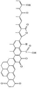
The right side of Fig. 6-1 is the surface of the GC, and the left side is the GC bulk. Various functional groups containing oxygen atoms such as carbonyl, hydroxyl, carboxyl, catechol, p-quinone, lactone etc., are dispersed on the electrode surface.

On such kind of GC electrode surface, the influence for the redox reaction varies with the type of the molecular species. Oxygen amount evaluation by XPS, the O/C ratio is 10% to 14% immediately after polishing, and can be reduced to less than 2% by various surface treatments (vacuum heat treatment, polishing in cyclohexane, hydrogen plasma treatment, etc.
Although these processes themselves are practically meaningless, they are important in terms of understanding the properties of the electrode surface.

McCreery etc. are summarizing the procedures for evaluating GC electrodes as shown in Fig. 6-1.).
                         Schematic representation of GC surface after polishing
    Fig. 6-1 Schematic representation of GC surface after polishing

Ru(NH3)63+/2+, IrCl63-/2-, Co(phen)33+/2+, Fe(phen)33+/2+, Co(en)33+/2+, Dopamine (D(DA), 4-methyl catechol (4-MC), Dihydroxyphenylacetic acid (DOPAC), Fe(CN)63-/4-, ferrocene, viologens, ascorbic acid (AA), Anthraquinone disulfate (AQDSD) etc., are used as test substances to evaluate and investigate the electrode characteristics.
 
These substrates have been used as redox indicators and the mediators for understating the redox potential of electrochemically active proteins (Ref. 6-1, 6-2).

The electron transfer of outer-sphere electron transfer type molecular species does not have much dependence to the electrode surface state (monolayer adsorption, presence or absence of oxygen functional group, etc.).

Ferro-ferricyanide is usually regarded as an outer-sphere type, but it seems not be capable for GC electrodes.

In fact, it should be noted that ferro-ferricyanide is actually very sensitive to the state of the electrode surface. On the other hand, the presence of adsorption sites formed by hydrogen bonds via OH groups is important for dopamine and NADH etc.
 Schematics of GC Surface evaluation procedures
    Fig. 6-2 Schematics of GC Surface evaluation procedures.

Besides, the hydrate ion of Fe2+/3+, Eu2+/3+ and V2+/3+ greatly depend on the presence or absence of a carbonyl group.
 
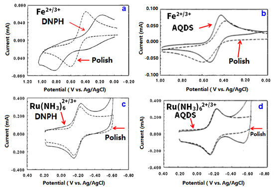
For example, the mono-layer molecular modification with dinitrophenyl hydrazine (DNPH) to crush the carbonyl group on the surface, the electron transfer of the outer-sphere electron transfer type Ru(NH3)62+/3+ is hardly affected (Fig. 6-3-c,d) but the electron transfer of Fe2+/3+ is changed to be extremely slow (Fig. 6-2-a). However, with adsorption of carbonyl group containing AQDS, the electron transfer of Fe2+/3+ is faster than non- adsorption on the GC electrode surface (Fig. 6-2-b) addition, the redox reaction of Fe2+/3+is not much affected after the hydroxyl group crushing treatment with dinitrobenzyl chloride,due to the carbonyl groups remain (Ref. 6-3).
 Comparison of CVs
    Fig. 6-3 Comparison of CVs of Fe2+/3+ and Ru(NH3)62+/3+ with polished surface and modified surface.


References:
6-1) Electroanalytical Chemistry17, 221—374 , (1991).
6-2) R.L.McCreery, Chem. Rev.108, 2646, (2008).
6-3) P.Chen, M.A.Fryling and R.L.McCreery, Anal. Chem.67, 3115, (1995).

 
Glassy carbon electrode surface impurity adsorption and countermeasures

7. Glassy carbon electrode surface impurity adsorption and countermeasures

Laboratory Of Research & Development, BAS Inc.
Professor Noriyuki Watanabe


McCreery et al. indicate that impurities contained in commercially available general organic solvent may possibly be adsorbed to the GC electrode and interfere with the electrochemical measurement. As a countermeasure, they recommend to purify the solvent before handling by using activated carbon, immersing the polished GC electrode in an activated carbon dispersed solvent for pre-cleaning. When GC electrode is immersed for a while in isopropanol with activated carbon dispersed, the impurities adsorbed to GC during polishing process are effectively removed by overwhelmingly large surface area of activated carbon adsorption.

An example for oxidation detection of 1 mM ascorbic acid in 0.1 M sulfuric acid by cyclic voltammetry (0.1 V/s) is shown in Fig. 7-1. Although the electron transfer reaction of ascorbic acid is fast, it is a typical example of EC reaction type and is chemically irreversible.

The solid line is for polished GC electrode, the dotted line is for isopropanol cleaned GC electrode, and the dashed line is for isopropanol containing activated carbon cleaned GC electrode, respectively in Fig. 7-1.
                        Comparison of cyclic voltammograms of ascorbic acid measured by different cleaning treatment GC electrodes.
Fig. 7-1 Comparison of cyclic voltammograms of ascorbic acid measured by different cleaning treatment GC electrodes.

The oxidation peak potential of ascorbic acid at isopropanol cleaned GC electrode (Fig. 7-1, dotted line) shifts 200 mV to the positive direction comparing with the polished GC electrode (Fig. 7-1, solid line), indicating its electron transfer is slower than the polished GC electrode.

However, the oxidation peak potential of ascorbic acid using activated carbon depredated isopropanol solvent cleaned GC electrode (Fig. 7-1, dashed line) which shifts to the negative direction comparing with polished GC electrode (Fig. 7-1, solid line), indicating that electron transfer becomes faster than the polished electrode, because impurities adsorbed at the GC electrode surface are removed by adsorption to the activated carbon.
 
Let’s see another example (Fig. 7-2). Anthraquinone disulfate (AQDS) is easily adsorbed by the GC electrode surface, which is an electrode active material itself, it is a convenient substance when you want to investigate adsorption.

Cyclic voltammetry measurement for 40 µM AQDS in 0.1 M HClO4using polished (solid line), acetonitrile cleaned (dotted line) and acetonitrile containing activated carbon cleaned (dashed line) GC electrodes are compared and shown in Fig. 7-2.

The CV profile exhibits a typical adsorption peak shape which has less attenuation from diffusion, and the small redox peak potential difference. In this case as well as in the previous example, comparing with the polished GC electrode, the peak area of just solvent cleaned GC electrode is decreased. Because the adsorption sites have already been occupied by the impurities in organic solvent, that AQDS can not be adsorbed on GC. Whereas, the peak area is doubled for the GC electrode which cleaned by acetonitrile containing activated carbon (Fig. 7-2, dashed line).
Comparison of differed cleaning pretreatment GC electrodes for AQDS adsorption redox reactions.
Fig. 7-2 Comparison of differed cleaning treatment GC electrodes for AQDS adsorption redox reactions..

The relevant paper regarding the interferences due to impurities in organic solvents and the validity of activated carbon as a countermeasure is shown in below (Ref. 7-1).

References:
7-1) S.Ranganathan, T.C.Kuo and McCreery, ibid.71, 3574, (1999).


Adsorption of catechol and derivatives on glassy carbon electrode and electron transfer rate

8. Adsorption of catechol and derivatives on glassy carbon electrode and electron transfer rate

Laboratory Of Research & Development, BAS Inc.
Professor Noriyuki Watanabe

The electrochemistry regarding Quinone-hydroquinone including Catechol has been continuously studied for many years and it is an important theme spanning various related fields. Recently there is also an interesting report by D. H. Evans et al.8-3). Perhaps that story might touch either, relating to carbon electrode surface treatment, this time the introduction subject is also selected from literatures of McCreery et al. (8-1 - 8-2).
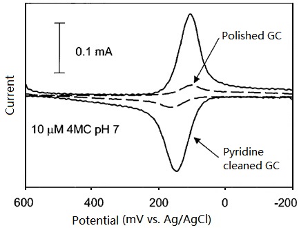
In previous technical note, it was mentioned that GC electrode activity could be improved by activated carbon depredated organic solvent cleaning, also the pyridine cleaning could achieve to same result. At pyridine cleaned GC electrode, not only the electron transfer rate of 4-methylcatechol increases but also its adsorption on electrode increases significantly.

As shown in Fig. 8-1, the cyclic voltammogram of 10 µM 4-methylcatechol (pH=1) micro sample has a major feature of diffusive wave on polished only GC electrode, in comparison, on the further pyridine cleaned GC electrode, CV has a major adsorbent wave with a minor diffusive wave in features, the decrease of redox peak potential difference range could be noticed. The catechol adsorption on GC electrode plays an important role in electron transfer, is the theme of this issue. The below two experimental results may support this opinion.
                        Cyclic voltammograms of 1 µM 4-methylcatechol (pH=1) at polished only and further pyridine cleaned GC electrodes respectively.
Fig. 8-1 Cyclic voltammograms of 1 µM 4-methylcatechol (pH=1) at polished only and further pyridine cleaned GC electrodes respectively.


One is that on the GC electrode with trifluoromethylphenyl (TFMP) monomolecular film modification, the electron transfer rate of catechol dwindles significantly (the peak potential width becomes quite wider than 60 mV of general one-electron reversible system), till the electron transfer becomes unobserved at all. This feature is obviously different from other outer-sphere electron transfer molecules (outer-sphere electron transfer molecules are hardly affected by the electrode surface state. Even if they are affected, the change in current is about 2 to 10 times at mostly, but in the case of catechol, the tremendous change is in digits, for example 1000 times.).

For example, on the trifluoromethylphenyl group (TFMP) coated GC electrode, the electron transfer of dopamine (DA) abruptly slows corresponding to TFMP coating ratio increase (It may be found from the significant increase of the peak potential width in Fig. 8-2).
                        Cyclic voltammograms of 1 mM dopamine in 0.1 M H2SO4 solution on GC electrodes with various TMPF coating ratio (0.12, 0.16, 0.25 ).
Fig. 8-2 Cyclic voltammograms of 1 mM dopamine in 0.1 M H2SO4 solution on GC electrodes with various TFMP coating ratio (0.12, 0.16, 0.25).

Such an obvious decrease of electron transfer rate may also be achieved by the adsorption of mono-molecules such as methylene blue.


However, in the case of catechol derivative molecules such as quinone adsorption, the electron transfer rate of dopamine and 4-methylcatechol just decreases slightly, although their adsorption is disturbed (Fig. 8-3). This is the second reason.

On catechol analogue duroquinone monomolecular adsorbed electrode, the peak potential width of dopamine (comparing with the activated carbon cleaned electrode) has a little increase. On the other hand, the methylene blue monomolecular adsorption is notablely different (Waves at potential range from 200 mV to negative are due to the adsorption of methylene blue and duroquinone in Fig. 8-3). Thus, the adsorption of quinone including adsorption of catechol itself plays a major role in electron transfer of catechol.
                        Cyclic voltammograms of 1 mM dopamine (pH = 1)on glassy carbon electrodes with different surface treatments (activated carbon cleaned, duroquinone adsorbed and methylene blue adsorbed).
Fig. 8-3 Cyclic voltammograms of 1 mM dopamine (pH = 1) on glassy carbon electrodes with different surface treatments (activated carbon cleaned, duroquinone adsorbed and methylene blue adsorbed).

References:
8-1) S.H. DuVall and R.L. McCreery, Anal. Chem.71, 4594, (1999)
8-2) S.H. DuVall and R.L. McCreery, J. Am. Chem. Soc.,122, 6759, (2000)
8-3) A. Rene and D,H. Evans, J. Phys. Chem. C116, 14454, (2012)

We dispatch worldwide

For purchases that exceeds $100

OFF

Discount Electrodes

Safe Site

We protect your data