It is well know that a potentiostat is essential in electrochemical measurements.
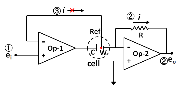
From what you see, the reason why the counter electrode and the working electrode must be connected to completely different points in terms of circuit inside the potentiostat can be understood.
As mentioned in previous "Counter Electrode" technical note, in the case of two-electrodes system, it is difficult to differentiate between the counter electrode and the working electrode, whereas in three-electrodes system using potentiostat, they are clearly distinguished.
Last time , the potentiostat could be theoretically consisted by the combination of at least two operational amplifiers, the establishment of three fundamental functions (①, the working electrode potential regulation versus the reference electrode, ② measuring the current flowing through the working electrode, ③ no current flowing to the reference electrode), and the points for understanding the function of Op amp (both of input terminals had the same voltage and the input impedance was too large that the current could not flow in or flow out of the Op amp within two input terminals.) were demonstrated.
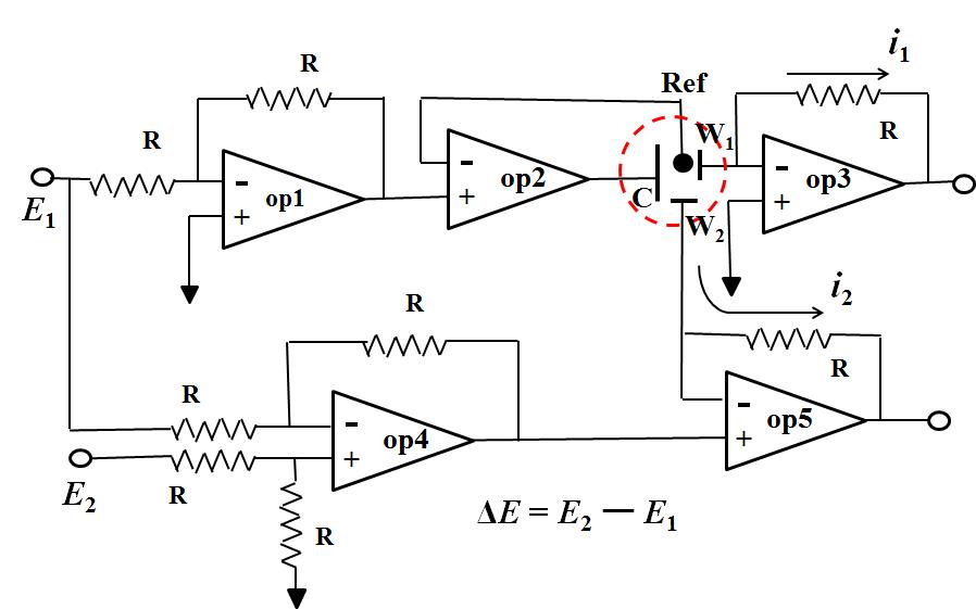
Fig.2 is five Op amps used circuit diagram of bi-potentiostat. The potential of the working electrode 1 (W1) is controlled by Op amp1 and Op amp2 which is same as previously described (only one Op amp used in the previous artical), the regulated potential is E1. Op amp4 is a subtraction circuit which outputs the difference signal between E1 and E2, while becomes the + input terminal of the OP amp5 (signal difference ΔE = E2 - E1). Because the voltages of the + input terminal and the - input terminal are the same (described previously), the potential applied to the working electrode 2 is E2 - E1. E1 is the potential applied to the electrode 1, E2 can completely be selected independently. Therefore, the electrode 2 can be independently controlled.
In this manner, for example of RRDE, it is possible to apply an arbitrary potential independently for the disk electrode and the ring electrode respectively versus the common reference electrode.
Two points in final. One point is a voltage follower. Op Amp 2 is it. Since there is no else connection route to the + terminal except the signal from the former stage (Op amp 1) it has almost no current flow. Since the ─ terminal is the only connection to the reference electrode, there is no current flow over there, whereas the current can flow as the amplifier output (it is connected to the counter electrode C and becomes electrolytic current). This causes the possibility to pass a large current without current flow, that is, impedance conversion is performed. It is used frequently in potentiostat.
Another one point is a subtraction circuit and an addition circuit. In the subtraction circuit, it may be difficult to clearly understand the feature that there is no mutual interference between input signals, for the addition circuit, variables to be added are connected to the same input terminal, so it is easy to convince its effect.
The effective use of addition circuit for the solution resistance compensation positive feedback will be discussed in next edition.
In the previous two editions, the potentiostat was talked and the continuation will be presented. The positive feedback is a topic here. This is an optional function which is not always necessary, but you may select to use it, if you need.
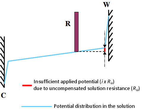
This is commonly called uncompensated solution resistance and is marked as Ru. It can be schematically depicted as shown in Fig. 3.1. It shows the state when the current i flows a cell. Subscript u comes from the meaning of either “unkown” or “uncontrollable”.
Even with a potentiostat, such potential drop can not be controlled completely. The only alternative is to deal with incomplete methods with positive feedback as described below.
The unfavorable effect caused by this uncompensated solution resistance is, for example, a peak potential shift and an extra spread of the peak potential width in a CV (Cyclic Voltammetry) measurement.
The deviation of the peak potential causes a difference between the absolute values of the oxidation peak current and the reduction peak current, and the redox potential estimated from the average of the two peak potentials will slightly deviate. Besides, the electron transfer speed calculated from the peak potential width will be slower. For this reason, it is necessary to reduce the effect of uncompensated solution resistance. The method is positive feedback.
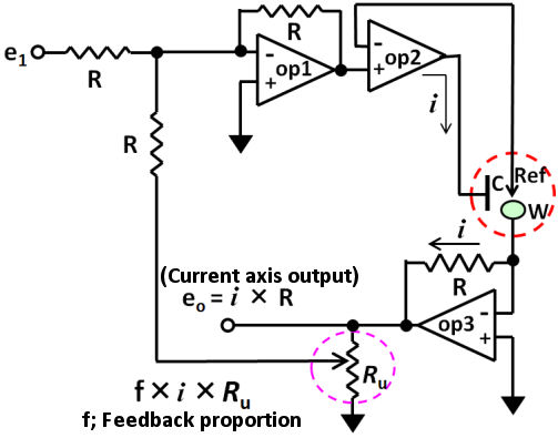
The positive feedback circuit can be configured with three op amps as shown in Fig. 3.2. An additive circuit (op 1) is added to the prototype basic circuit (configured by two op amp) prototype which was mentioned before.
In last issue, the positive feedback and the potentiostat might measure the uncompensated solution resistance (Ru) was mentioned, whereas, considering there might be some people want to know how the potentiostat could measure the Ru, therefore, we would like to make it clear in this issue.

Zf is the Faraday impedance related to the redox reaction of active species (not considering the diffusion impedance of active species) in solution.
The solution resistance includes the resistance (Rs) between the counter electrode and the reference electrode, and the resistance (Ru) between the reference electrode and the working electrode, which across the reference electrode (usually represented by Rs, Ru respectively). The potentiostat can consider the Rs but can not recognize the Ru (therefore, the potential drop due to the product of the current flowing in the cell and the uncompensated solution resistance i x Ru can’t be controlled by the potentiostat.).
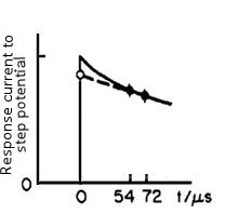
The response current can be expressed by an exponential function with the time constant of RuCdl (the below equation).
When t = 0, the exponential function is 1, so i(0) = ΔE / Ru. That is, if the current value is obtained immediately after the potential applying, as the ΔE is a set value and is known (for example, when set to 50 mV), the value of Ru can be obtained.
The current value at time zero is measured in the manner as shown in Fig. 4-2, that is the current value at two points after the potential step (52 and 72 microseconds in Fig. 4-2) are measured and approximated by extrapolating it to zero time.
When the time constant of the cell (given by Ru × Cdl) is smaller than the rise time of the potentiostat, the error may be large, whatever, such a case means that Ru is small and is almost no need for the iR compensation.
Positive feedback is done using solution resistance Ru obtained in this way. Since Ru is much affected by the position of the reference electrode, it is desirable to place it as near as possible to the working electrode and be careful not to vary for each measurement. Under the minute current of the microelectrode, since the influence is small, the problem of solution resistance is small. In the bulk electrolysis with large current amount, there is a margin in potential setting, so there are relatively less problems. Please note that iR compensation causes instability of the potentiostat, if it is large amount of compensation.
A method using CV to obtain electron transfer rate (ks),which announced about 50 years ago is usually used (Ref. 5-1).
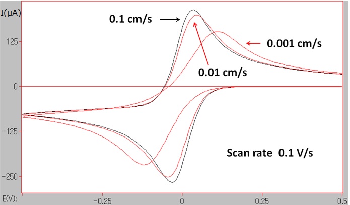
Examining such kinetic parameter as well as investigating the redox potential which is a thermodynamic parameter, are the important objectives in electrochemical measurements.
Incidentally, the peak potential width (ΔEp) does not only change due to the electron transfer rate, but also the uncompensated solution resistance may greatly influence it. So far this has been mentioned several times.
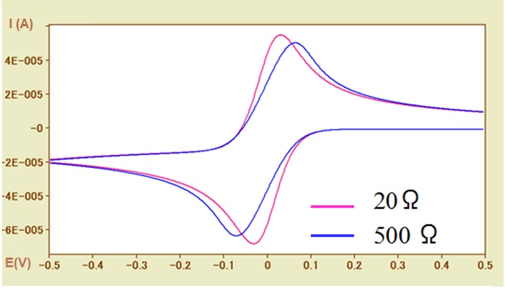
Such situation can be shown in Figure 5-2. by CV simulation.
In the case of a fast electron transfer rate reaction system (ks = 0.1 cm / s), the CV curves of the uncompensated solution resistances of 20Ω (pink line) and 500Ω (blue line) are compared. With the increase of the solution resistance, the widening of the peak potential width (ΔEp) has a dependence on the solution resistance, which similar to the influence of the electron transfer rate, can be observed. The necessary of examining whether the solution resistance has influence in determining the electron transfer rate should be noted here.
In addition, the redox potential is calculated using the average value of the peak potential. However, the potential difference between the oxidation peak and the reduction peak is caused by the solution resistance, and thus the possibility of inequality should be considered also (although it is a trivial matter). In other words, the absolute values of the oxidation and reduction peak current values of are usually not exactly the same.
In Fig. 5-2, the baseline current of the oxidation peak is negative value, so the absolute value of the oxidation peak current is less than that of the reduction peak current with the zero baseline current.
Since the influence of the solution resistance on the potential shift is effective at the current (I) × solution resistance (R) (IR drop) result, therefore the current value is also quite important. By reducing the concentration of the electroactive species, or decreasing the electrode surface area (in the extreme case, the microelectrode can be used), etc. to reduce the current value, then to judge whether there is any effect of the solution resistance.
Reference:
5-1)R. S. Nicholson, Anal. Chem.,37, 1351 (1965)
One of the purposes of the electrochemical measurement is to understand the redox potential of the subject. Oxidation-reduction potential is a characteristic feature of molecules that can be used for the identification and characterization of the substances. That is how to determine the redox potential. If you know this, you can use it as a guide to designing a substance with a desired redox potential.
The outer layer electrons of the substance (considering molecular species here) occupy the electronic energy level (also called orbital) in the turn from the low level to high level. The highest occupied energy level is defined as the highest occupied level (HOMO; Highest Occupied Molecular Orbital), the unoccupied energy level above it is called the lowest unoccupied molecular orbital (LUMO:Lowest Unoccupied Molecular Orbital), these electronic energy levels are involved in the reaction of molecular species.
For this reason, HOMO and LUMO are also called frontier levels. Regarding electrochemical reactions, oxidation is to remove electrons from HOMO, and reduction is to add electrons to LUMO.
Because the electronic level is the inherent feature of the substance, the redox potential is also a unique value of the substance. Formally, it is called standard oxidation reduction potential or formula amount oxidation reduction potential, but here it is expressed as redox potential (redox is a combination of reduction and oxidation).
As the redox potential of a molecular species depends on the locations of the HOMO - LUMO, it is possible to obtain it by theoretically quantum mechanical calculation. However, it may also be significance to understand which factors affect redox potential in quality. For this reason, it will be described in several times later.
HOMO, LUMO may determine the redox potential and cause the redox potential fluctuation. The fluctuation factor for the electronic energy level is mainly the electron density in the redox center (the site where electron transfer takes place), the electric charge around it (positive, negative, its size), and the influence of the medium is added as other factor too. When an organometallic compound is used as a material, its characterization can be considered.
Firstly, let’s consider the increase or decrease of the electron density of the redox center (site). For example, when the electron density of the redox center increases due to the influence of a substituent (electron-donating group), the electron level rises (becomes unstable), and the redox potential easily shifts to the negative direction, which makes it easy to be oxidized. On the other hand, if the electron density is lowered by a substituent (electron-withdrawing group), the opposite situation will occur.
For an example, let’s compare the acetyl group and the methyl group as the substituents of the ferrocene. The former acetyl group is electron-withdrawing group and reduces the electron density around iron which is a redox site, and methyl group is an electron donating group. Their effectiveness is almost directly proportional to the number of the substituents. The redox potential of ferrocene is shifted to the positive in 0.25 V when one acetyl substituent and 0.47 V positive shift when diacetyl group substituent. On the other hand, there is negative shift of 500mV when deca-methyl substituted ferrocene (when all hydrogen atoms are replaced by methyl groups). A negative shift of 50 mV is caused by per methyl group.
They two persons were responsible for the synthesis and purification of ferrocene and several ferrocene derivatives, ruthenocene and osmocene. At that time, cyclic voltammetry was not popular as it is now, and Kuwana adopted Chronopotentiometry (CP) which recorded the change of the working electrode potential versus time by applying a constant current flow. Although CP is not often used today, no need for the electrode potential feedback control, and once the electrode potential could be recorded correctly, it is a sufficiently simple method. The redox potential can be obtained from the transition time of CP.
At the beginning, Kuwana used a mercury electrode, however because of the too large background current flow, a platinum electrode was used as an alternative working electrode. At that time, his supervisor was Ralph Adams, a well-known pioneer of solid electrodes research work, replacing the working electrode with a platinum electrode was a natural thing.
Interestingly, there was no name of supervisor in Kuwana's paper. The details including this anecdote can be found in Bill Geiger's reviews 7-4). Recently, I (Watanabe) emailed Kuwana and received the reply from him. A partial of the reply was cited as “We did most of the work over Easter holiday. The faculty graciously let us publish without their names on the papers. Generous and unusual, needless to say.”. It was also an interesting paper that revealed the importance of the redox potential of the ferrocene could be controlled by substituents.
Reference:
7-1) Wilkinson,G., J.Am.Chem.Soc. 74, 6146, & 6148, (1952)
7-2) Page,J.A., Wilkinson,G. J.Am.Chem.Soc., 74,6149,(1952)
7-3) Kuwana,T.,Bublitz,D.E., Hoh,G. J.Am.Chem.Soc., 82, 5811, (1960)
7-4) Geiger W.E., Organometallics 26, 5738 (2007)
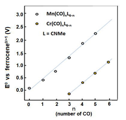 Fig. 8-1 The redox potential change of the manganese and chromium compounds when carbonyl groups substitute methyl isocyanate
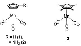
The reversible redox potential of cyclopentadienyl manganese tricarbonyl (1) is 0.92 V vs. ferrocene reference.
The IR spectrum in the carbonyl region during the bulk electrolytic oxidation is shown in Fig.8-3.
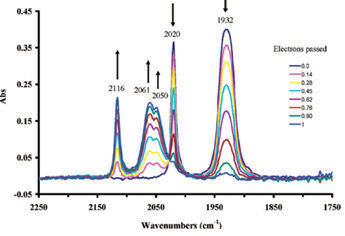
With electrolytic oxidation proceeding, the absorption intensity of two peaks belonging to 1 at the low wavenumber side (1930 cm-1, 2020 cm-1) are decreased, meanwhile three peaks (2050 cm-1, 2061 cm-1, 2116 cm-1) belonging to 1+ appear at the high wave number side, and their absorption intensity increase gradually.
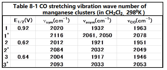
Electrolytic oxidation causes the electron intensity decreasing around the manganese, thus the electron back donation is decreased. Therefore, the Mn-CO bond is weakened; on country indicate the enhancement of the CO bond. The redox potentials of compounds 2 and 3 (Fig. 8-2) with amino or methyl substitutions on cyclopentenyl rings are in the negative direction comparing with compound 1.
This is due to the electron supplied property of the substituents, which increases the electron back donation from the central metal to the ligand CO, and the wavenumber of CO shifts to be low, in the IR spectrum of the CO stretching frequency (see below table).
Reference:
8-1) W.E. Geiger et al., J. Am. Chem. Soc., 130, 9859 (2008)